My Cheap & Simple Optocoupler based DC Motor Driver for 3.3v Devices
So, as you know, I have been dealing with foam hobby planes for a long time. And I have finally decided to build a mini club flier to help me train for flying my 2-meter glider. But to build those, I would always need some way to power/control the motor, and always the 3.3v devices failed to power them. I lacked cheap motor drivers or an esc for these small motors, so usually I ended up quitting projects that involved flight (unless I saved enough money to buy escs and powerful motors, which only happened once). But this ends today, because today I will show you a super simple motor driver I made!
Ok, so how this will work is that I will use a Photocoupler (Optocoupler) to control a much higher voltage circuit (which is the circuit running the motor).
What is an Optocoupler
Well, in short terms, it is a device that uses light to transfer a signal from one circuit to another, all while being voltage independent from the other circuit.
In one end of the sensor, there is a built-in LED, which is turned on with a signal. Then this light will turn on a “transistor-like” electronic switch that is activated via light.
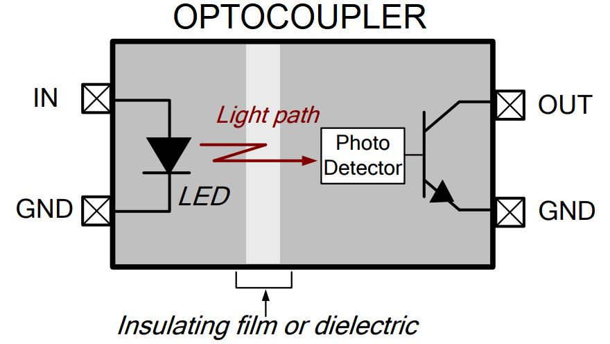
As, you can see, with the image above and below, this is a device that allows you to control two electrical systems, completely independent of voltage levels!!
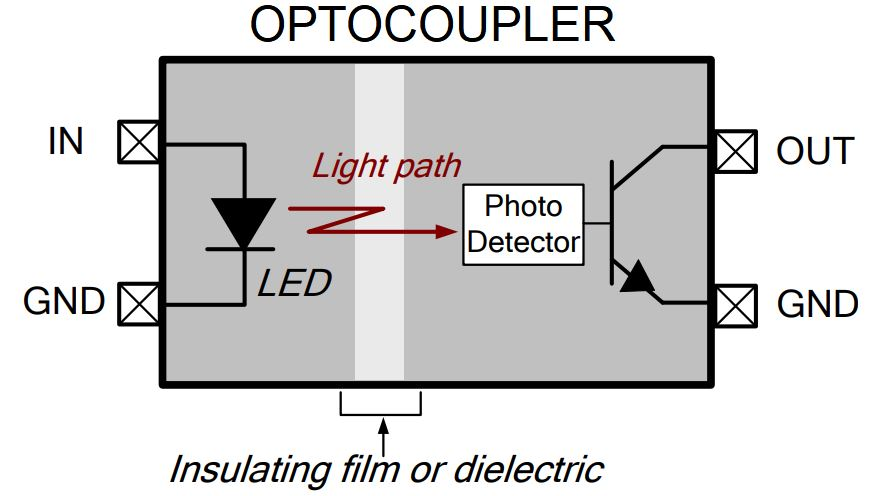
This is really usefull to me, as I am not in the situation right now to spend more money on electronic components (like an ESC, or MOSFETs).
Ok, now for the actual build.
So, first I prototyped the devices on my breadboard using a Raspberry Pi Pico (because this was the computer I planned on using):
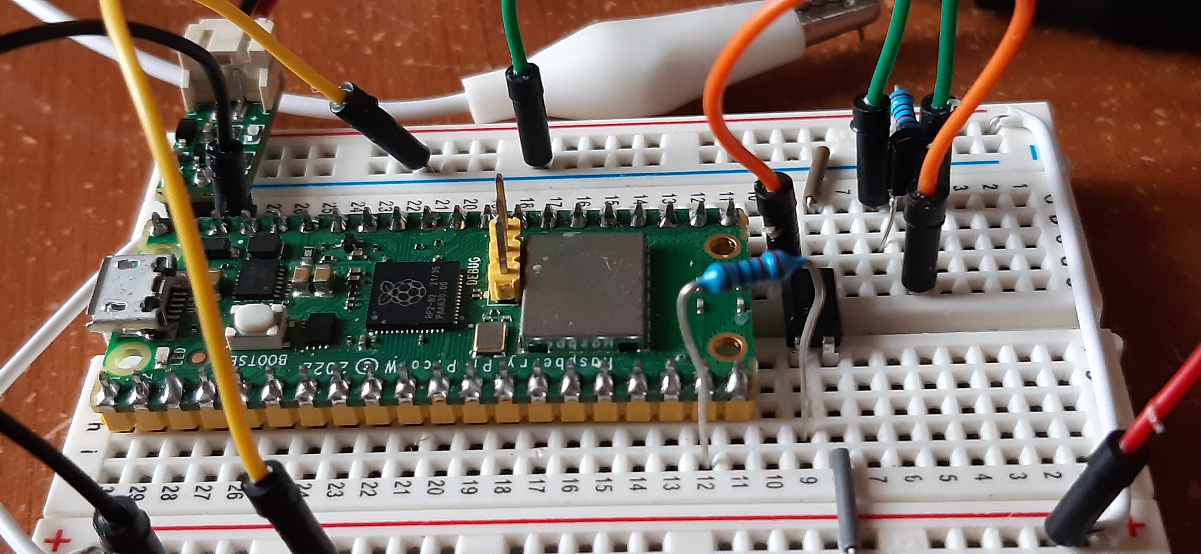
And if you would like to see an explanation of this, here is a video:
Ok, anyways, here is a diagram of the circuit:
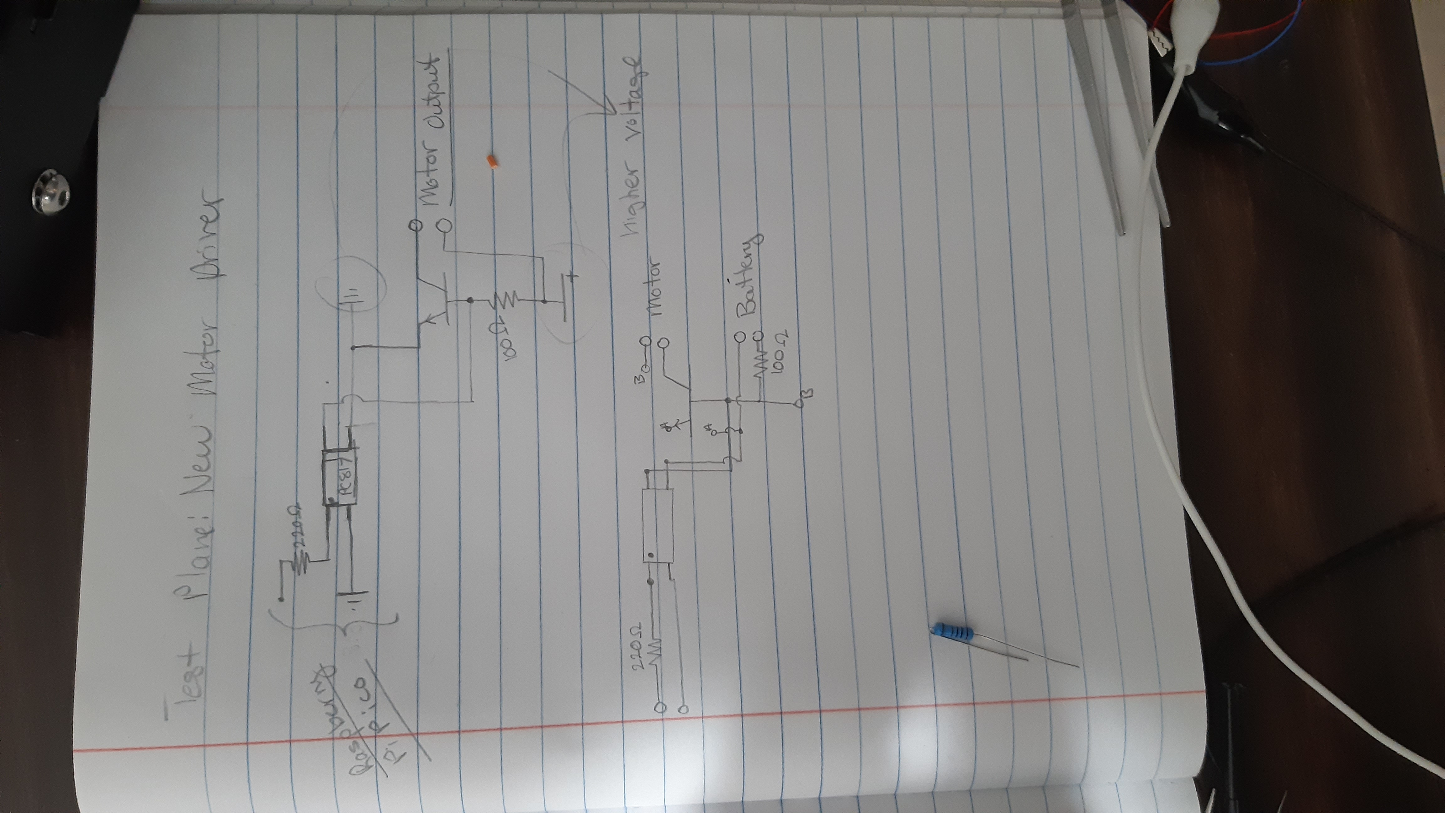
This circuit has been the result of much researching, experimentation, and a bit of luck. But finally, I arrived at the above circuit I designed.
Now, be careful (as this was something I did when I transferred this over to the actual device, which caused me a lot of pain after words), please do’t put a very low resistance on the transistor capacitor (R2). Because if you put, say a 100 ohms, then the circuit will not work.
How it works, it after the optocpuler is activated, it allows negative ground to flow to the base of the NPN transistor, which shuts off the gate , turning the motor off.
Below, is the code I used to PWM the speed of the motor (I used Thonny with MicroPython to program the Pi Pico):
import machine
from machine import PWM
import utime
from time import sleep

motor1A = machine.Pin(14, machine.Pin.OUT)
motor2A = machine.Pin(15, machine.Pin.OUT)

pwm = PWM(motor1A)

duty_step = 129  # Step size for changing the duty cycle

#Set PWM frequency
frequency = 5000
pwm.freq (frequency)

def clockwise():
    motor1A.high()
    motor2A.low()

def anticlockwise():
    motor1A.low()
    motor2A.high()

def stopMotor():
    motor1A.low()
    motor2A.low()

while True:
    for duty_cycle in range(0, 65536, duty_step):
        pwm.duty_u16(duty_cycle)
        sleep(0.05)
    # Decrease the duty cycle gradually
    for duty_cycle in range(65536, 0, -duty_step):
        pwm.duty_u16(duty_cycle)
        sleep(0.05)
This code works by creating a PWM object, on a certain pin (which is the one the optocouler will be attached to). We then set the duty_step to 129 and the frequency to 5000. This will basically determine the type of digital wave we will be creating. How fast will this occur in a given amount of time? How fast will we change the ratio? And so on.
And with those, we loop through the various duty_cycles (which will determine the ratio of 1 to 0), incrementing by duty_step; we then feed this into the output pin using this function, which should achieve a PWM signal:
pwm.duty_u16(duty_cycle)
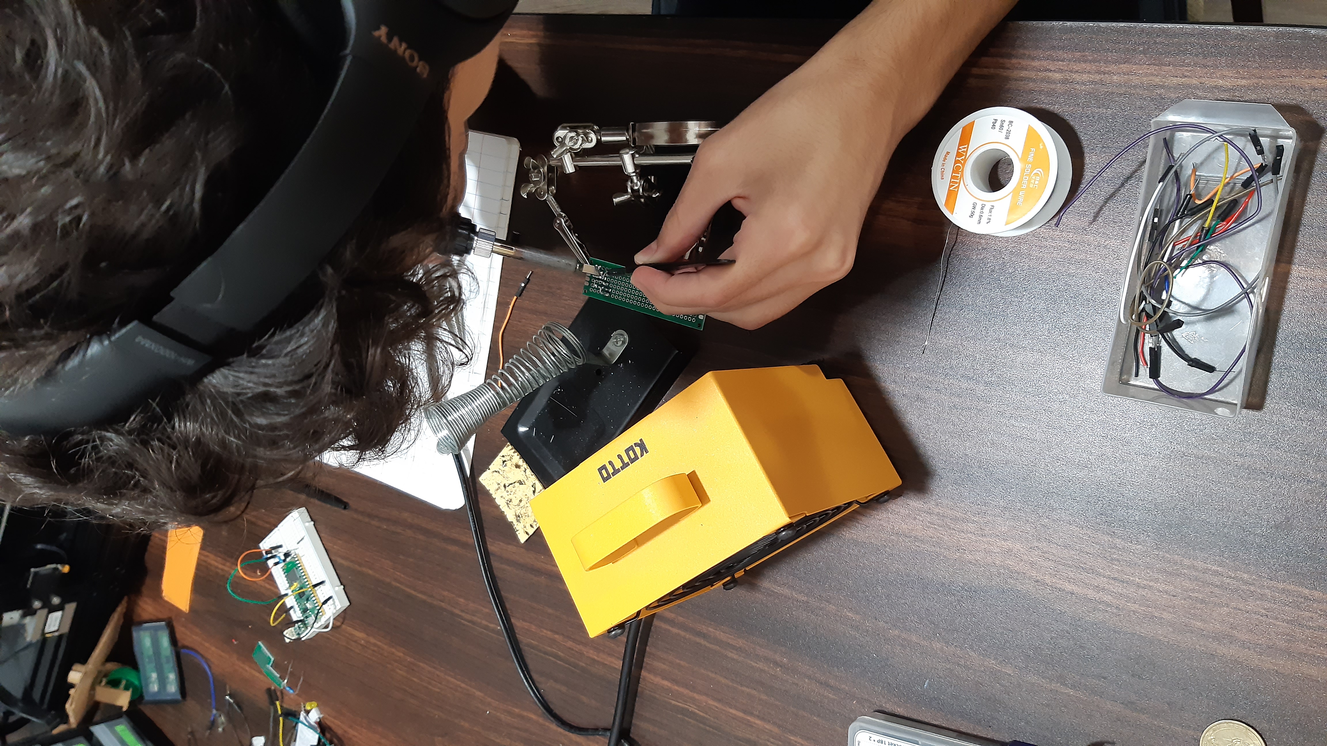
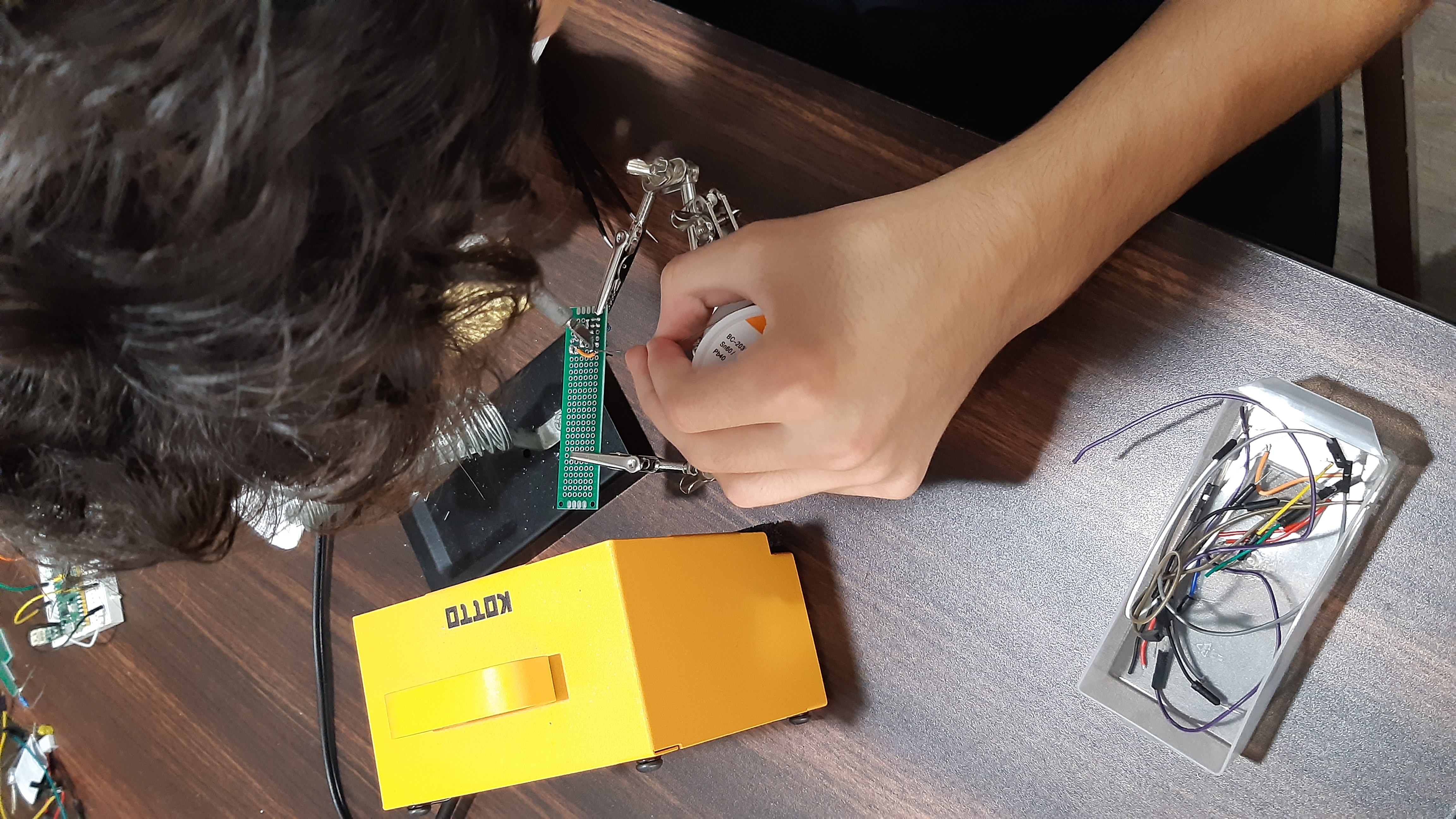
And here are some images to me soldering on this device:
As you can see below, there are 3 pairs of pins, the 1 that is by itself, is the input one (where the Pi Pico will attach itself). Then, on the top-right to the image, is the motor output, where the two leads of the motor will attach. And on the top-left, that is the motor power’s input (it can be any voltage the transistor and motor can take!). Cool right?
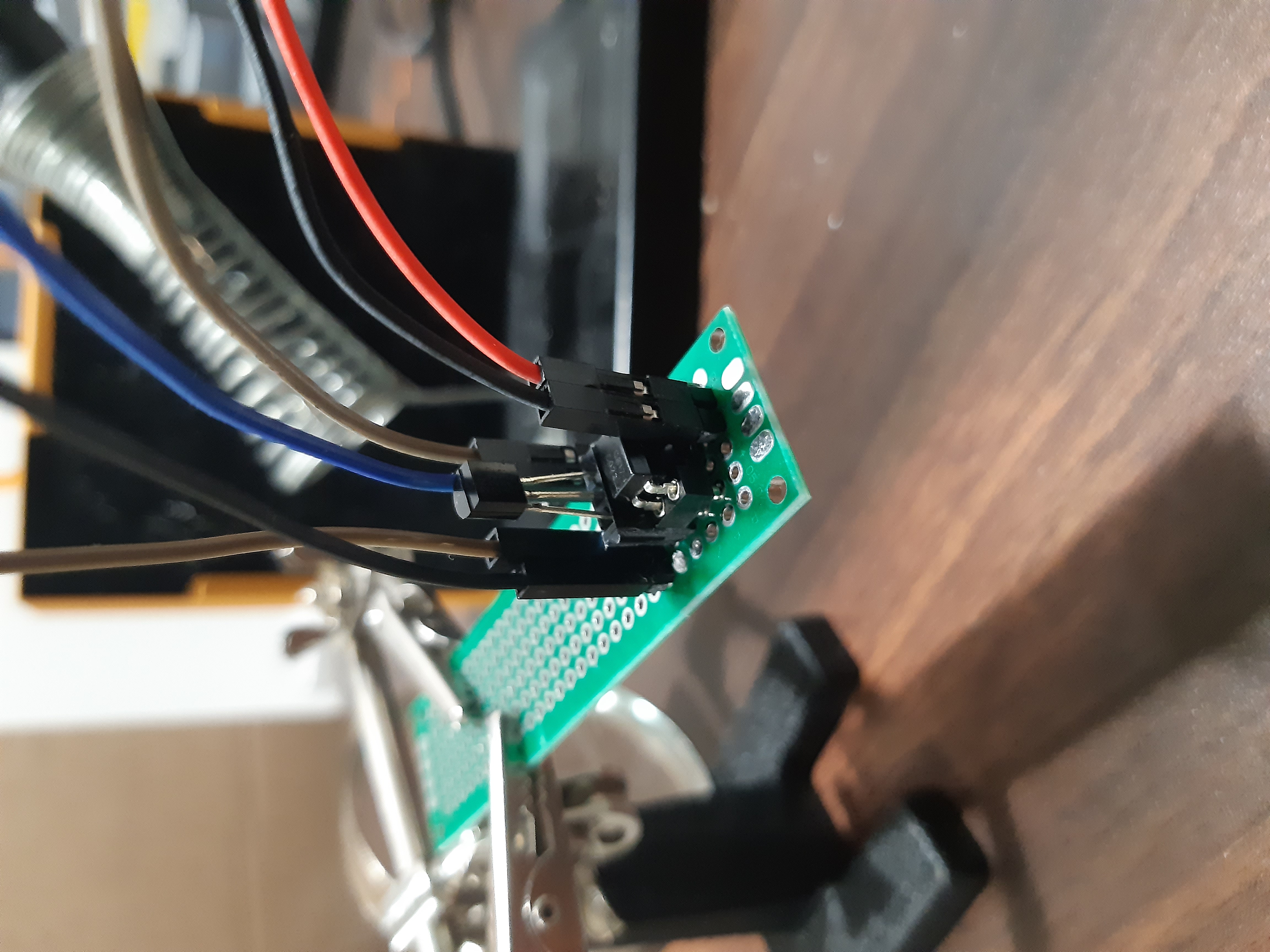
With this tiny controller, we can PWM control really powerful motors, with like 12 volts, all by controlling a 3.3v pin on the Pi Pico!!!
I plan to use this extensively in future projects, and I hope this was helpful to you in some way.
Thanks, and I will see you next time!!
Subscribe to Burak Ayyorgun
Get the latest posts delivered right to your inbox